MGER实验
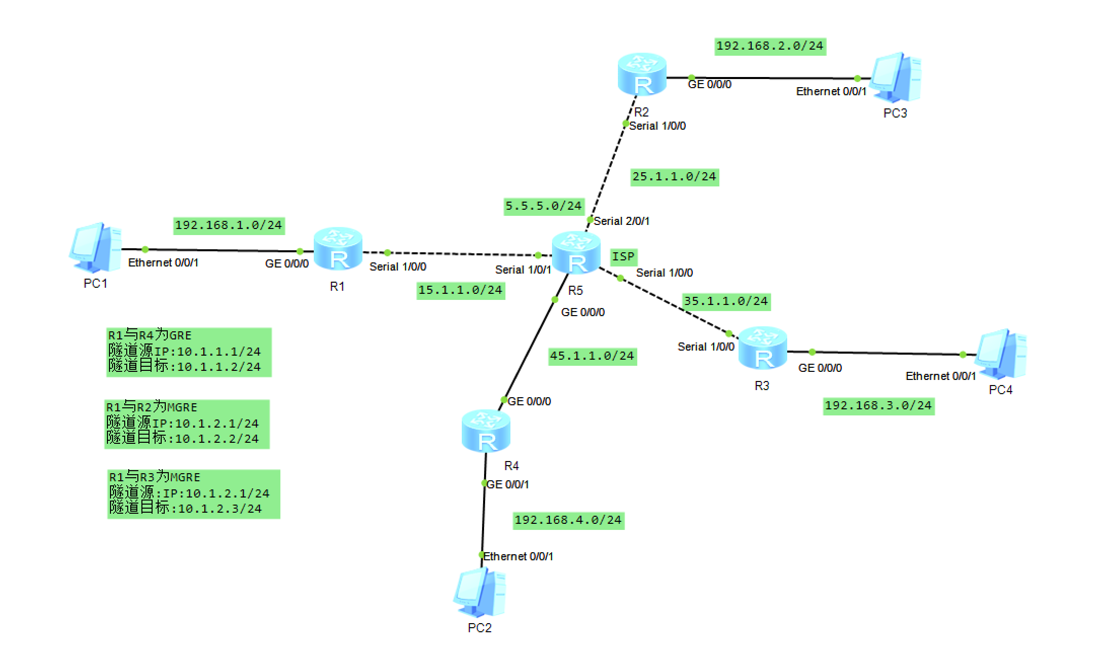
一、实验拓扑
二、实验需求
1、R5为ISP,只能进行IP地址配置,其所有地址均配为公有IP地址;
2、R1和R5间使用PPP的PAP认证,R5为主认证方;R2与R5之间使用ppp的CHAP认证,R5为主认证方;R3与R5之间使用HDLC封装;
3、R1、R2、R3构建一个MGRE环境,R1为中心站点,R1、R4间为点到点的GRE; 4、R1.整个私有网络基本RIP全网可达; 5、所有PC设置私有IP为源IP,可以访问R5环回。
三、实验思路
1、分配IP
2、创建缺省
3、R1和R5间使用PPP的PAP认证,R5为主认证方
4、R2与R5之间使用ppp的CHAP认证,R5为主认证方
5、R3与R5之间使用HDLC封装;
6、R1、R2、R3构建一个MGRE环境,R1为中心站点,R1、R4间为点到点的GRE;
7、R1整个私有网络基本RIP全网可达;
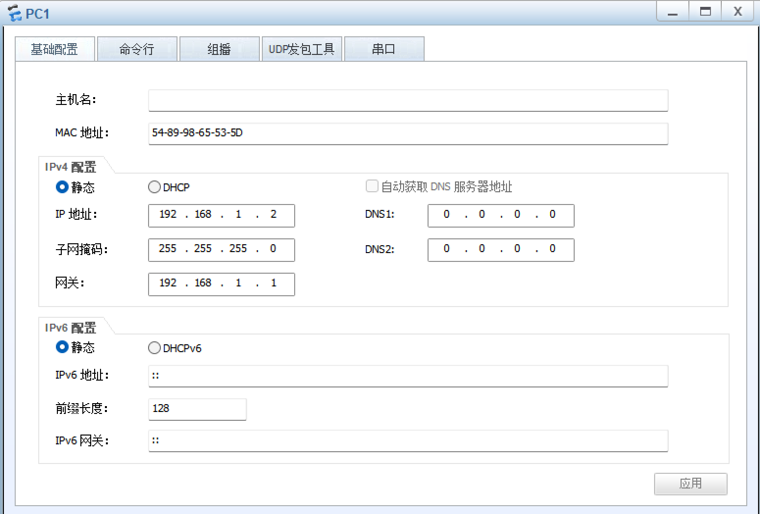
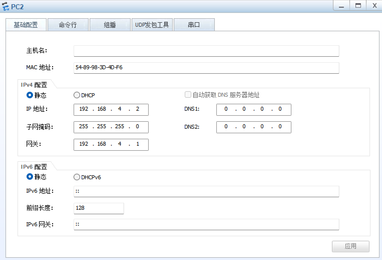
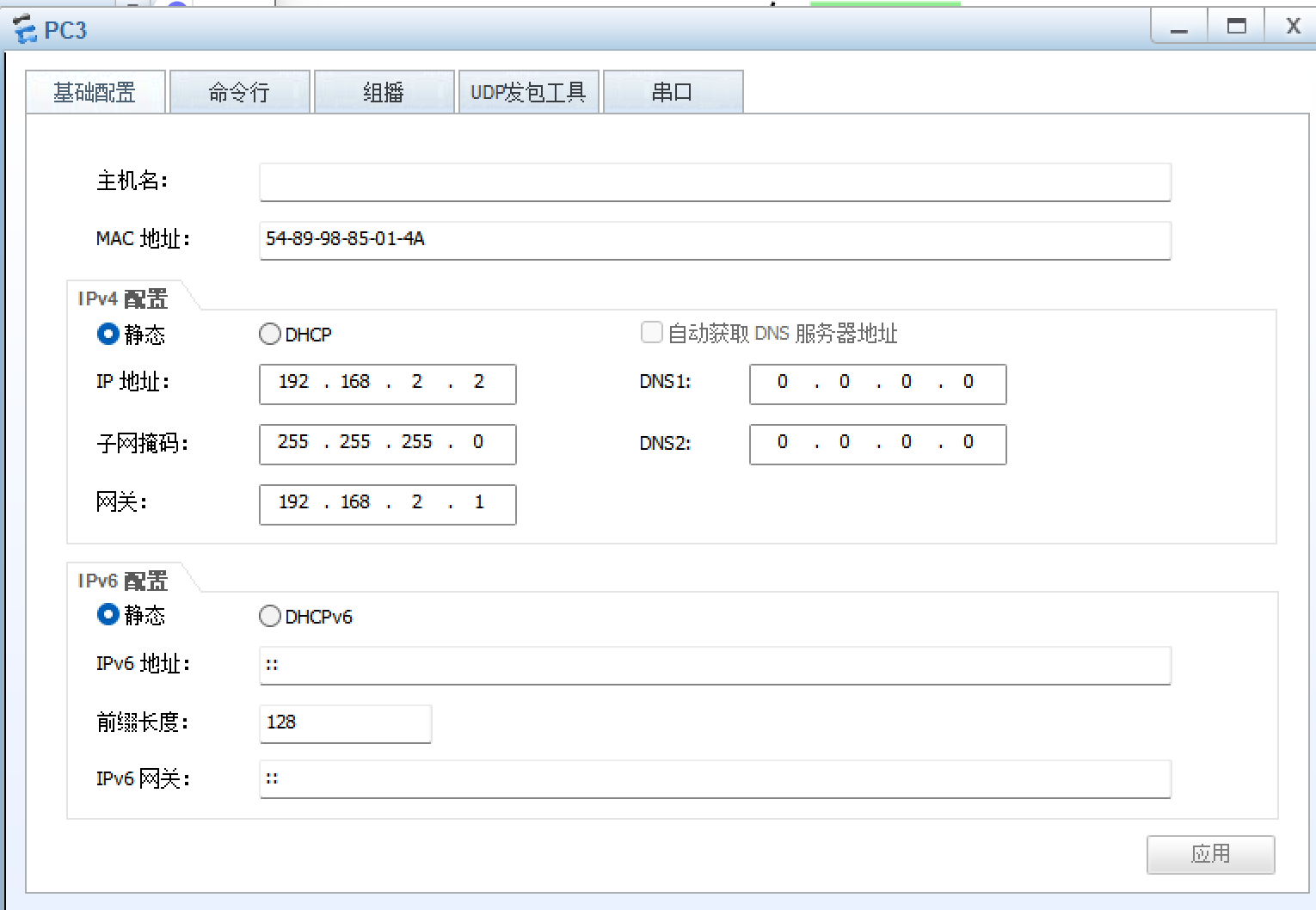
8、所有PC设置私有IP为源IP,可以访问R5环回
四、实验步骤
1、分配IP
R1:
[R1]INT G 0/0/0
[R1-GigabitEthernet0/0/0]IP add 192.168.1.1 24
[R1-GigabitEthernet0/0/0]
Jul 26 2025 20:04:04-08:00 R1 %%01IFNET/4/LINK_STATE(l)[0]:The line protocol IP
on the interface GigabitEthernet0/0/0 has entered the UP state.
[R1-GigabitEthernet0/0/0]int s 1/0/0
[R1-Serial1/0/0]ip add 15.1.1.1 24
[R1-Serial1/0/0]q
[R1]dis ip int b
*down: administratively down
^down: standby
(l): loopback
(s): spoofing
The number of interface that is UP in Physical is 3
The number of interface that is DOWN in Physical is 4
The number of interface that is UP in Protocol is 3
The number of interface that is DOWN in Protocol is 4Interface                         IP Address/Mask      Physical   Protocol
GigabitEthernet0/0/0              192.168.1.1/24       up         up
GigabitEthernet0/0/1              unassigned           down       down
NULL0                             unassigned           up         up(s)
Serial1/0/0                       15.1.1.1/24          up         up
R2:
[R2]int g 0/0/0
[R2-GigabitEthernet0/0/0]ip add 192.168.2.1 24
Jul 26 2025 20:07:00-08:00 R2 %%01IFNET/4/LINK_STATE(l)[10]:The line protocol IPon the interface GigabitEthernet0/0/0 has entered the UP state.
[R2-GigabitEthernet0/0/0]int s 1/0/0
[R2-Serial1/0/0]ip add 25.1.1.1 24
[R2-Serial1/0/0]q
[R2]dis ip int b
*down: administratively down
^down: standby
(l): loopback
(s): spoofing
The number of interface that is UP in Physical is 3
The number of interface that is DOWN in Physical is 4
The number of interface that is UP in Protocol is 3
The number of interface that is DOWN in Protocol is 4Interface                         IP Address/Mask      Physical   Protocol
GigabitEthernet0/0/0              192.168.2.1/24       up         up
GigabitEthernet0/0/1              unassigned           down       down
NULL0                             unassigned           up         up(s)
Serial1/0/0                       25.1.1.1/24          up         up
R3:
[R3]int g 0/0/0
[R3-GigabitEthernet0/0/0]ip add 192.168.3.1 24
Jul 26 2025 20:10:15-08:00 R3 %%01IFNET/4/LINK_STATE(l)[0]:The line protocol IP
on the interface GigabitEthernet0/0/0 has entered the UP state.
[R3-GigabitEthernet0/0/0]int s 1/0/0
[R3-Serial1/0/0]ip add 35.1.1.1 24
[R3-Serial1/0/0]q
[R3]dis ip int b
*down: administratively down
^down: standby
(l): loopback
(s): spoofing
The number of interface that is UP in Physical is 3
The number of interface that is DOWN in Physical is 4
The number of interface that is UP in Protocol is 3
The number of interface that is DOWN in Protocol is 4Interface                         IP Address/Mask      Physical   Protocol
GigabitEthernet0/0/0              192.168.3.1/24       up         up
GigabitEthernet0/0/1              unassigned           down       down
NULL0                             unassigned           up         up(s)
Serial1/0/0                       35.1.1.1/24          up         up
R4:
[R4]int g 0/0/1
[R4-GigabitEthernet0/0/1]ip add 192.168.4.1 24
Jul 26 2025 20:12:54-08:00 R4 %%01IFNET/4/LINK_STATE(l)[0]:The line protocol IP
on the interface GigabitEthernet0/0/1 has entered the UP state.
[R4-GigabitEthernet0/0/1]int g 0/0/0
[R4-GigabitEthernet0/0/0]ip add 45.1.1.1 24
Jul 26 2025 20:13:43-08:00 R4 %%01IFNET/4/LINK_STATE(l)[1]:The line protocol IP
on the interface GigabitEthernet0/0/0 has entered the UP state.
[R4-GigabitEthernet0/0/0]q
[R4]dis ip int b
*down: administratively down
^down: standby
(l): loopback
(s): spoofing
The number of interface that is UP in Physical is 3
The number of interface that is DOWN in Physical is 4
The number of interface that is UP in Protocol is 3
The number of interface that is DOWN in Protocol is 4Interface                         IP Address/Mask      Physical   Protocol
GigabitEthernet0/0/0              45.1.1.1/24          up         up
GigabitEthernet0/0/1              192.168.4.1/24       up         up
NULL0                             unassigned           up         up(s)
R5:
[R5]int s 1/0/1
[R5-Serial1/0/1]ip add 15.1.1.2 24
[R5-Serial1/0/1]
Jul 26 2025 20:16:33-08:00 R5 %%01IFNET/4/LINK_STATE(l)[0]:The line protocol PPPIPCP on the interface Serial1/0/1 has entered the UP state.
[R5-Serial1/0/1]int g 0/0/0
[R5-GigabitEthernet0/0/0]ip add 45.1.1.2 24
Jul 26 2025 20:17:16-08:00 R5 %%01IFNET/4/LINK_STATE(l)[1]:The line protocol IP
on the interface GigabitEthernet0/0/0 has entered the UP state.
[R5-GigabitEthernet0/0/0]int s 2/0/1
[R5-Serial2/0/1]ip add 25.1.1.2 24
[R5-Serial2/0/1]
Jul 26 2025 20:18:05-08:00 R5 %%01IFNET/4/LINK_STATE(l)[2]:The line protocol PPPIPCP on the interface Serial2/0/1 has entered the UP state.
[R5-Serial2/0/1]int s 1/0/0
[R5-Serial1/0/0]ip add 35.1.1.2 24
[R5-Serial1/0/0]
Jul 26 2025 20:19:17-08:00 R5 %%01IFNET/4/LINK_STATE(l)[3]:The line protocol PPPIPCP on the interface Serial1/0/0 has entered the UP state.
[R5-Serial1/0/0]q
[R5]int l 0
[R5-LoopBack0]ip add 5.5.5.5 24
[R5-LoopBack0]q
[R5]dis ip int b
*down: administratively down
^down: standby
(l): loopback
(s): spoofing
The number of interface that is UP in Physical is 6
The number of interface that is DOWN in Physical is 2
The number of interface that is UP in Protocol is 6
The number of interface that is DOWN in Protocol is 2Interface                         IP Address/Mask      Physical   Protocol
GigabitEthernet0/0/0              45.1.1.2/24          up         up
GigabitEthernet0/0/1              unassigned           down       down
LoopBack0                         5.5.5.5/24           up         up(s)
NULL0                             unassigned           up         up(s)
Serial1/0/0                       35.1.1.2/24          up         up
Serial1/0/1                       15.1.1.2/24          up         up
Serial2/0/0                       unassigned           down       down
Serial2/0/1                       25.1.1.2/24          up         up
2、创建缺省
R1:
[R1]ip route-static 0.0.0.0 0 15.1.1.2
R2:
[R2]ip route-static 0.0.0.0 0 25.1.1.2
R3:
[R3]ip route-static 0.0.0.0 0 35.1.1.2
R4:
[R4]ip route-static 0.0.0.0 0 45.1.1.2
3、R1和R5间使用PPP的PAP认证,R5为主认证方
R5:
[R5]aaa
[R5-aaa]local-user nzz password cipher 123456
[R5-aaa]local-user nzz service-type ppp
[R5-aaa]q
[R5]int s 1/0/1
[R5-Serial1/0/1]ppp authentication-mode pap
[R5-Serial1/0/1]shutdown
[R5-Serial1/0/1]undo shutdown
R1:
[R1]int s 1/0/0
[R1-Serial1/0/0]ppp pap local-user nzz password cipher 123456
测试:
[R1-Serial1/0/0]ping 15.1.1.2PING 15.1.1.2: 56 data bytes, press CTRL_C to breakReply from 15.1.1.2: bytes=56 Sequence=1 ttl=255 time=30 msReply from 15.1.1.2: bytes=56 Sequence=2 ttl=255 time=20 msReply from 15.1.1.2: bytes=56 Sequence=3 ttl=255 time=20 msReply from 15.1.1.2: bytes=56 Sequence=4 ttl=255 time=20 msReply from 15.1.1.2: bytes=56 Sequence=5 ttl=255 time=20 ms--- 15.1.1.2 ping statistics ---5 packet(s) transmitted5 packet(s) received0.00% packet lossround-trip min/avg/max = 20/22/30 ms[R5-Serial1/0/1]ping 15.1.1.1PING 15.1.1.1: 56 data bytes, press CTRL_C to breakReply from 15.1.1.1: bytes=56 Sequence=1 ttl=255 time=50 msReply from 15.1.1.1: bytes=56 Sequence=2 ttl=255 time=30 msReply from 15.1.1.1: bytes=56 Sequence=3 ttl=255 time=20 msReply from 15.1.1.1: bytes=56 Sequence=4 ttl=255 time=20 msReply from 15.1.1.1: bytes=56 Sequence=5 ttl=255 time=20 ms--- 15.1.1.1 ping statistics ---5 packet(s) transmitted5 packet(s) received0.00% packet lossround-trip min/avg/max = 20/28/50 ms
4、R2与R5之间使用ppp的CHAP认证,R5为主认证方
R5:
[R5]int s 2/0/1
[R5-Serial2/0/1]ppp authentication-mode chap
[R5-Serial2/0/1]shutdown
[R5-Serial2/0/1]undo shutdown
R2:
[R2]int s 1/0/0
[R2-Serial1/0/0]ppp chap user nzz
[R2-Serial1/0/0]ppp chap password cipher 123456
测试:
[R2-Serial1/0/0]ping 25.1.1.2PING 25.1.1.2: 56 data bytes, press CTRL_C to breakReply from 25.1.1.2: bytes=56 Sequence=1 ttl=255 time=30 msReply from 25.1.1.2: bytes=56 Sequence=2 ttl=255 time=20 msReply from 25.1.1.2: bytes=56 Sequence=3 ttl=255 time=30 msReply from 25.1.1.2: bytes=56 Sequence=4 ttl=255 time=20 msReply from 25.1.1.2: bytes=56 Sequence=5 ttl=255 time=20 ms--- 25.1.1.2 ping statistics ---5 packet(s) transmitted5 packet(s) received0.00% packet lossround-trip min/avg/max = 20/24/30 ms[R5-Serial2/0/1]ping 25.1.1.1PING 25.1.1.1: 56 data bytes, press CTRL_C to breakReply from 25.1.1.1: bytes=56 Sequence=1 ttl=255 time=40 msReply from 25.1.1.1: bytes=56 Sequence=2 ttl=255 time=20 msReply from 25.1.1.1: bytes=56 Sequence=3 ttl=255 time=20 msReply from 25.1.1.1: bytes=56 Sequence=4 ttl=255 time=20 msReply from 25.1.1.1: bytes=56 Sequence=5 ttl=255 time=20 ms--- 25.1.1.1 ping statistics ---5 packet(s) transmitted5 packet(s) received0.00% packet lossround-trip min/avg/max = 20/24/40 ms
5、R3与R5之间使用HDLC封装;
R3:
[R3]int s 1/0/0
[R3-Serial1/0/0]link-protocol hdlc
Warning: The encapsulation protocol of the link will be changed. Continue? [Y/N]
:Y
Jul 26 2025 20:52:59-08:00 R3 %%01IFNET/4/CHANGE_ENCAP(l)[0]:The user performed
the configuration that will change the encapsulation protocol of the link and th
en selected Y.
R5:
[R5]int s 1/0/0
[R5-Serial1/0/0]link-protocol hdlc
Warning: The encapsulation protocol of the link will be changed. Continue? [Y/N]
:y
Jul 26 2025 20:57:00-08:00 R5 %%01IFNET/4/CHANGE_ENCAP(l)[5]:The user performed
the configuration that will change the encapsulation protocol of the link and th
en selected Y.
测试:
[R5-Serial1/0/0]ping 35.1.1.1PING 35.1.1.1: 56 data bytes, press CTRL_C to breakReply from 35.1.1.1: bytes=56 Sequence=1 ttl=255 time=40 msReply from 35.1.1.1: bytes=56 Sequence=2 ttl=255 time=20 msReply from 35.1.1.1: bytes=56 Sequence=3 ttl=255 time=20 msReply from 35.1.1.1: bytes=56 Sequence=4 ttl=255 time=10 msReply from 35.1.1.1: bytes=56 Sequence=5 ttl=255 time=30 ms--- 35.1.1.1 ping statistics ---5 packet(s) transmitted5 packet(s) received0.00% packet lossround-trip min/avg/max = 10/24/40 ms[R3-Serial1/0/0]ping 35.1.1.2PING 35.1.1.2: 56 data bytes, press CTRL_C to breakReply from 35.1.1.2: bytes=56 Sequence=1 ttl=255 time=30 msReply from 35.1.1.2: bytes=56 Sequence=2 ttl=255 time=20 msReply from 35.1.1.2: bytes=56 Sequence=3 ttl=255 time=20 msReply from 35.1.1.2: bytes=56 Sequence=4 ttl=255 time=20 msReply from 35.1.1.2: bytes=56 Sequence=5 ttl=255 time=10 ms--- 35.1.1.2 ping statistics ---5 packet(s) transmitted5 packet(s) received0.00% packet lossround-trip min/avg/max = 10/20/30 ms6、R1、R2、R3构建一个MGRE环境,R1为中心站点,R1、R4间为点到点的GRE;
R1:
[R1]int Tunnel 0/0/0
[R1-Tunnel0/0/0]ip add 192.168.5.1 24
[R1-Tunnel0/0/0]tunnel-protocol gre p2mp
[R1-Tunnel0/0/0]source 15.1.1.1
[R1-Tunnel0/0/0]nhrp network-id 100
R2:
[R2]int Tunnel 0/0/0
[R2-Tunnel0/0/0]ip add 192.168.5.2 24
[R2-Tunnel0/0/0]tunnel-protocol gre p2mp
[R2-Tunnel0/0/0]source Serial 1/0/0
Jul 26 2025 21:11:50-08:00 R2 %%01IFNET/4/LINK_STATE(l)[0]:The line protocol IP
on the interface Tunnel0/0/0 has entered the UP state.
[R2-Tunnel0/0/0]nhrp network-id 100
[R2-Tunnel0/0/0]nhrp entry 192.168.5.1 15.1.1.1 register
R3:
[R3]int Tunnel 0/0/0
[R3-Tunnel0/0/0]ip add 192.168.5.3 24
[R3-Tunnel0/0/0]tunnel-protocol gre p2mp
[R3-Tunnel0/0/0]source Serial 1/0/0
Jul 26 2025 21:15:35-08:00 R3 %%01IFNET/4/LINK_STATE(l)[0]:The line protocol IP
on the interface Tunnel0/0/0 has entered the UP state.
[R3-Tunnel0/0/0]nhrp network-id 100
[R3-Tunnel0/0/0]nhrp entry 192.168.5.1 15.1.1.1 register
查看:
[R1]dis nhrp peer all
-------------------------------------------------------------------------------
Protocol-addr   Mask  NBMA-addr       NextHop-addr    Type         Flag
-------------------------------------------------------------------------------
192.168.5.2     32    25.1.1.1        192.168.5.2     dynamic      route tunnel
-------------------------------------------------------------------------------
Tunnel interface: Tunnel0/0/0
Created time    : 00:06:17
Expire time     : 01:53:43
-------------------------------------------------------------------------------
Protocol-addr   Mask  NBMA-addr       NextHop-addr    Type         Flag
-------------------------------------------------------------------------------
192.168.5.3     32    35.1.1.1        192.168.5.3     dynamic      route tunnel
-------------------------------------------------------------------------------
Tunnel interface: Tunnel0/0/0
Created time    : 00:02:41
Expire time     : 01:57:19Number of nhrp peers: 2
GRE配置:
R1:
[R1]int Tunnel 0/0/1
[R1-Tunnel0/0/1]ip add 192.168.6.1 24
[R1-Tunnel0/0/1]tunnel-protocol gre
[R1-Tunnel0/0/1]source 15.1.1.1
[R1-Tunnel0/0/1]destination 45.1.1.1
Jul 26 2025 21:48:05-08:00 R1 %%01IFNET/4/LINK_STATE(l)[0]:The line protocol IP
on the interface Tunnel0/0/1 has entered the UP state.
[R1-Tunnel0/0/1]q
[R1]rip 1
[R1-rip-1]network 192.168.6.0
R4:
[R4]int Tunnel 0/0/1
[R4-Tunnel0/0/1]ip add 192.168.6.2 24
[R4-Tunnel0/0/1]tunnel-protocol gre
[R4-Tunnel0/0/1]source 45.1.1.1
[R4-Tunnel0/0/1]destination 15.1.1.1
Jul 26 2025 21:49:57-08:00 R4 %%01IFNET/4/LINK_STATE(l)[0]:The line protocol IP
on the interface Tunnel0/0/1 has entered the UP state.
[R4-Tunnel0/0/1]q
[R4]rip 1
[R4-rip-1]version 2
[R4-rip-1]network 192.168.6.0
[R4-rip-1]network 192.168.4.0
测试:
[R1]ping 192.168.6.2PING 192.168.6.2: 56 data bytes, press CTRL_C to breakReply from 192.168.6.2: bytes=56 Sequence=1 ttl=255 time=40 msReply from 192.168.6.2: bytes=56 Sequence=2 ttl=255 time=40 msReply from 192.168.6.2: bytes=56 Sequence=3 ttl=255 time=40 msReply from 192.168.6.2: bytes=56 Sequence=4 ttl=255 time=30 msReply from 192.168.6.2: bytes=56 Sequence=5 ttl=255 time=20 ms--- 192.168.6.2 ping statistics ---5 packet(s) transmitted5 packet(s) received0.00% packet lossround-trip min/avg/max = 20/34/40 ms7、R1整个私有网络基本RIP全网可达;
R1:
[R1]rip 1
[R1-rip-1]version 2
[R1-rip-1]network 192.168.1.0
[R1-rip-1]network 192.168.5.0[R1]interface Tunnel 0/0/0
[R1-Tunnel0/0/0]nhrp entry multicast dynamic
[R1-Tunnel0/0/0]undo rip split-horizon
R2:
[R2]rip 1
[R2-rip-1]version 2
[R2-rip-1]network 192.168.2.0
[R2-rip-1]network 192.168.5.0
R3:
[R3]rip 1
[R3-rip-1]version 2
[R3-rip-1]network 192.168.3.0
[R3-rip-1]network 192.168.5.0
测试:
[R1]ping 192.168.3.1PING 192.168.3.1: 56 data bytes, press CTRL_C to breakReply from 192.168.3.1: bytes=56 Sequence=1 ttl=255 time=30 msReply from 192.168.3.1: bytes=56 Sequence=2 ttl=255 time=10 msReply from 192.168.3.1: bytes=56 Sequence=3 ttl=255 time=20 msReply from 192.168.3.1: bytes=56 Sequence=4 ttl=255 time=40 msReply from 192.168.3.1: bytes=56 Sequence=5 ttl=255 time=20 ms--- 192.168.3.1 ping statistics ---5 packet(s) transmitted5 packet(s) received0.00% packet lossround-trip min/avg/max = 10/24/40 ms[R1]ping 192.168.2.1PING 192.168.2.1: 56 data bytes, press CTRL_C to breakReply from 192.168.2.1: bytes=56 Sequence=1 ttl=255 time=30 msReply from 192.168.2.1: bytes=56 Sequence=2 ttl=255 time=30 msReply from 192.168.2.1: bytes=56 Sequence=3 ttl=255 time=40 msReply from 192.168.2.1: bytes=56 Sequence=4 ttl=255 time=30 msReply from 192.168.2.1: bytes=56 Sequence=5 ttl=255 time=30 ms--- 192.168.2.1 ping statistics ---5 packet(s) transmitted5 packet(s) received0.00% packet lossround-trip min/avg/max = 30/32/40 ms
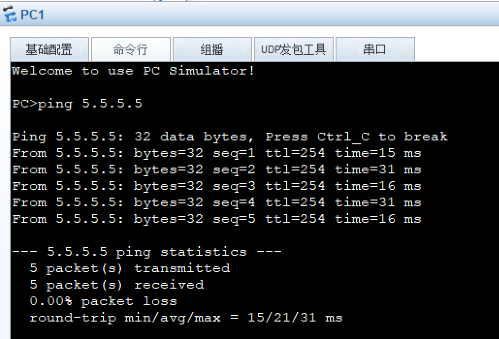
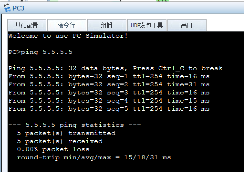
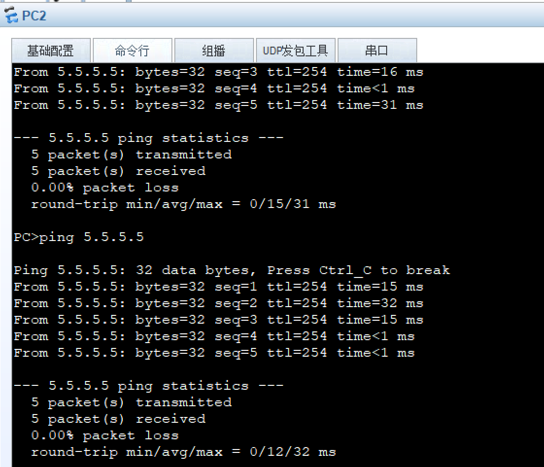
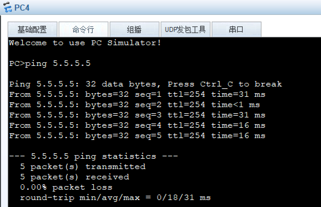
8、所有PC设置私有IP为源IP,可以访问R5环回

R1:
[R1]acl 2000
[R1-acl-basic-2000]rule permit source 192.168.1.0 0.0.0.255
[R1-acl-basic-2000]q
[R1]int s 1/0/0
[R1-Serial1/0/0]nat outbound 2000
R2:
[R2]acl 2000
[R2-acl-basic-2000]rule permit source 192.168.2.0 0.0.0.255
[R2-acl-basic-2000]q
[R2]int s 1/0/0
[R2-Serial1/0/0]nat outbound 2000
R3:
[R3]acl 2000
[R3-acl-basic-2000]rule permit source 192.168.3.0 0.0.0.255
[R3-acl-basic-2000]q
[R3]int s 1/0/0
[R3-Serial1/0/0]nat outbound 2000
R4:
[R4]acl 2000
[R4-acl-basic-2000]rule permit source 192.168.4.0 0.0.0.255
[R4-acl-basic-2000]q
[R4]int g 0/0/0
[R4-GigabitEthernet0/0/0]nat outbound 2000
五、测试