day15 SPI
1串行外设接口概述
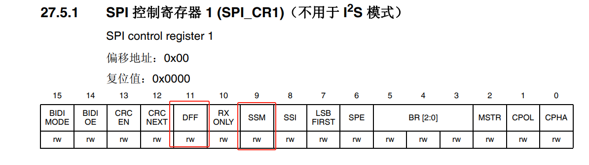
1.1基本概念
SPI(串行外设接口)是一种高速、全双工、同步的串行通信协议。串行外设接口一般是需要4根线来进行通信(NSS、MISO、MOSI、SCK),但是如果打算实现单向通信(最少3根线),就可以利用这种机制实现一对多或者一对一的通信。
1.2引脚定义
SPI总线采用的环形结构,利用的是主从模式(主机---->从机)进行数据的传输,由于是同步通信,所以在主机发送数据的同时也会收到从机发送的数据。
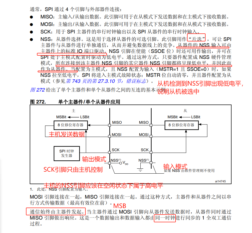
如果主机不打算和从机进行数据的传输,应该让NSS引脚在空闲状态下处于高电平(表示不通信),如果打算和某个从机进行单独通信的话,则需要把从机对应的NSS引脚拉低。
片选引脚之间是“互斥”的,同一时刻只能有一个片选引脚为低电平。
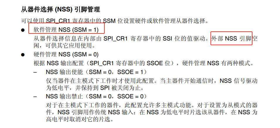
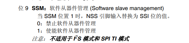
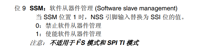
主设备和从设备都有片选引脚NSS/CS,通过片选引脚来实现主设备和多个从设备之间的通信,NSS片选引脚可以由软件控制,也可以由硬件控制。
1.3工作模式
由于SPI外设是全双工同步通信,所以时钟信号就由SCK引脚来生成,SCK引脚只能由主设备控制,从设备是无法控制的,所以SCK引脚输出的脉冲信号的极性和相位就需要进行配置。
时钟相位CPHA:置1 第二个边沿采集 置0 第一个边沿采集
时钟极性CPHL:置1 上升沿采样 置0 下降沿采样
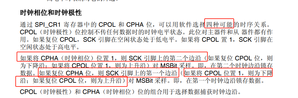
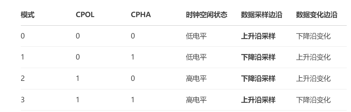
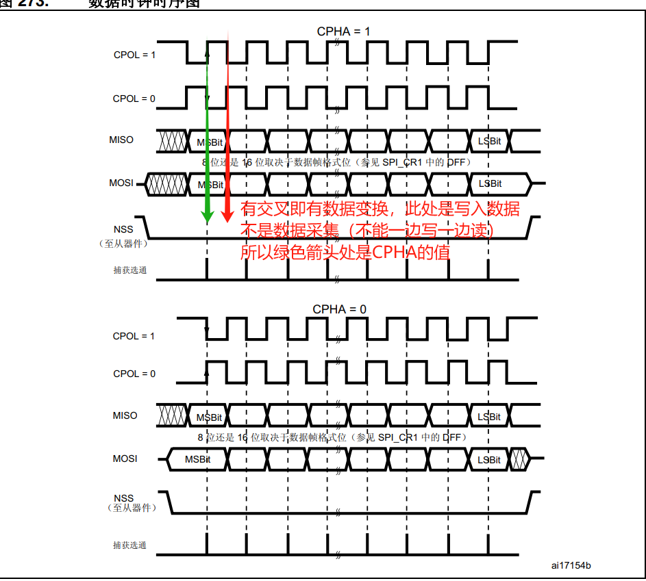
这两位可以得到四种不同的组合,就被作为SPI总线的工作模式(模式0~模式3),到底要选择哪种模式,主机的工作模式必须根据从设备的数据手册的说明进行设置。
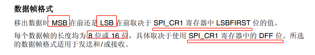
1.4 数据格式
主机与从机在通信的过程中传输的数据时以bit为单位(串行传输),所以数据格式就十分重要,主机的数据格式必须要根据从机的数据格式进行设置(MSB或者LSB)。

1.5通信速率:
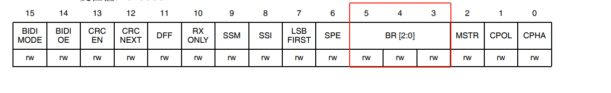
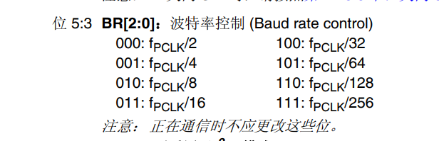
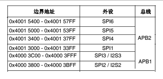
由图可知:SPI1挂载在APB2上,而APB1总线频率42MHZ,APB2总线频率84MHZ,BR寄存器用000模式下最多可以使用42MHZ频率,SPI2和SPI3也可以达到21Mbps,但是一些外围器件的通信速率最高也就是10Mbps左右,极少数可以超过10Mbps(W25Q128芯片)。
2SPI配置
2.1使用流程
可以参考stm32f4xx_spi.c的开头注释以及ST公司提供的代码例程,根据代码思路进行设计
===================================================================
##### How to use this driver #####
===================================================================
[..]
(#) Enable peripheral clock using the following functions
RCC_APB2PeriphClockCmd(RCC_APB2Periph_SPI1, ENABLE) for SPI1
1打开SPI外设的时钟
RCC_APB1PeriphClockCmd(RCC_APB1Periph_SPI2, ENABLE) for SPI2
RCC_APB1PeriphResetCmd(RCC_APB1Periph_SPI3, ENABLE) for SPI3
RCC_APB1PeriphResetCmd(RCC_APB1Periph_SPI3, ENABLE) for SPI4
RCC_APB1PeriphResetCmd(RCC_APB1Periph_SPI3, ENABLE) for SPI5
RCC_APB1PeriphResetCmd(RCC_APB1Periph_SPI3, ENABLE) for SPI6.
(#) Enable SCK, MOSI, MISO and NSS GPIO clocks using RCC_AHB1PeriphClockCmd()
function.2打开GPIO的外设时钟
In I2S mode, if an external clock source is used then the I2S
CKIN pin GPIO clock should also be enabled.
(#) Peripherals alternate function:
(++) Connect the pin to the desired peripherals' Alternate Function (AF)
using GPIO_PinAFConfig() function④引脚功能复用
(++) Configure the desired pin in alternate function by:
GPIO_InitStruct->GPIO_Mode = GPIO_Mode_AF配置复用模式
(++) Select the type, pull-up/pull-down and output speed via GPIO_PuPd,
GPIO_OType and GPIO_Speed members ③初始化GPIO
(++) Call GPIO_Init() function In I2S mode, if an external clock source is
used then the I2S CKIN pin should be also configured in Alternate
function Push-pull pull-up mode.
⑤配置SPI外设参数
(#) Program the Polarity, Phase, First Data, Baud Rate Prescaler, Slave
Management, Peripheral Mode and CRC Polynomial values using the SPI_Init()
function.
In I2S mode, program the Mode, Standard, Data Format, MCLK Output, Audio
frequency and Polarity using I2S_Init() function. For I2S mode, make sure
that either:
(++) I2S PLL is configured using the functions
RCC_I2SCLKConfig(RCC_I2S2CLKSource_PLLI2S), RCC_PLLI2SCmd(ENABLE) and
RCC_GetFlagStatus(RCC_FLAG_PLLI2SRDY); or
(++) External clock source is configured using the function
RCC_I2SCLKConfig(RCC_I2S2CLKSource_Ext) and after setting correctly
the define constant I2S_EXTERNAL_CLOCK_VAL in the stm32f4xx_conf.h file.
(#) Enable the NVIC and the corresponding interrupt using the function
SPI_ITConfig() if you need to use interrupt mode. 这个不用
(#) When using the DMA mode 这个不用
(++) Configure the DMA using DMA_Init() function
(++) Active the needed channel Request using SPI_I2S_DMACmd() function
(#) Enable the SPI using the SPI_Cmd() function or enable the I2S using
I2S_Cmd().⑥使能SPI
2.2代码展示
#include "stm32f4xx.h"
#include "stm32f4xx_spi.h"
#include "stm32f4xx_gpio.h"
#include "stm32f4xx_rcc.h"
void SPI1_Init(void) {
GPIO_InitTypeDef GPIO_InitStruct;
SPI_InitTypeDef SPI_InitStruct;
// 1. 使能时钟
RCC_AHB1PeriphClockCmd(RCC_AHB1Periph_GPIOA, ENABLE);
RCC_APB2PeriphClockCmd(RCC_APB2Periph_SPI1, ENABLE);
// 2. 配置GPIO(复用功能)
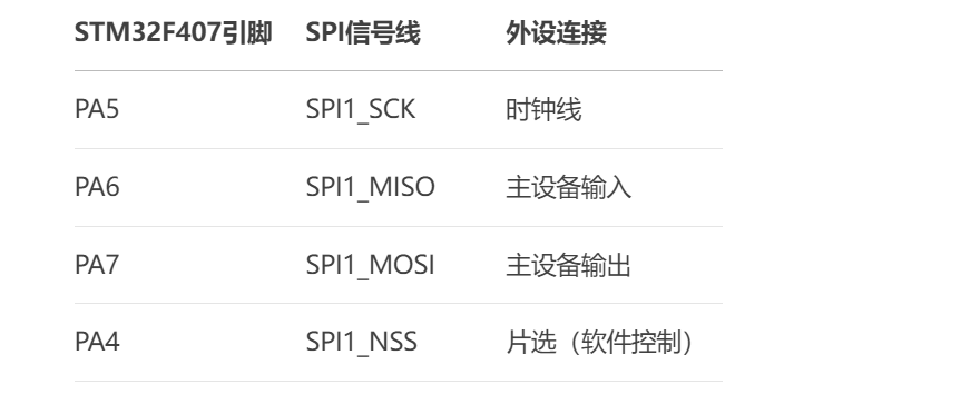
GPIO_InitStruct.GPIO_Pin = GPIO_Pin_5 | GPIO_Pin_6 | GPIO_Pin_7; // SCK, MISO, MOSI
GPIO_InitStruct.GPIO_Mode = GPIO_Mode_AF; // 复用模式
GPIO_InitStruct.GPIO_Speed = GPIO_Speed_50MHz;
GPIO_InitStruct.GPIO_OType = GPIO_OType_PP; // 推挽输出
GPIO_InitStruct.GPIO_PuPd = GPIO_PuPd_NOPULL;
GPIO_Init(GPIOA, &GPIO_InitStruct);
// 映射GPIO到SPI功能
GPIO_PinAFConfig(GPIOA, GPIO_PinSource5, GPIO_AF_SPI1); // SCK
GPIO_PinAFConfig(GPIOA, GPIO_PinSource6, GPIO_AF_SPI1); // MISO
GPIO_PinAFConfig(GPIOA, GPIO_PinSource7, GPIO_AF_SPI1); // MOSI
// 3. 配置片选引脚(PA4,普通GPIO输出)
GPIO_InitStruct.GPIO_Pin = GPIO_Pin_4;
GPIO_InitStruct.GPIO_Mode = GPIO_Mode_OUT;
GPIO_InitStruct.GPIO_OType = GPIO_OType_PP;
GPIO_InitStruct.GPIO_Speed = GPIO_Speed_50MHz;
GPIO_Init(GPIOA, &GPIO_InitStruct);
GPIO_SetBits(GPIOA, GPIO_Pin_4); // 默认拉高(不选中)
// 4. 配置SPI参数
SPI_InitStruct.SPI_Direction = SPI_Direction_2Lines_FullDuplex; // 全双工
SPI_InitStruct.SPI_Mode = SPI_Mode_Master; // 主模式
SPI_InitStruct.SPI_DataSize = SPI_DataSize_8b; // 8位数据
SPI_InitStruct.SPI_CPOL = SPI_CPOL_Low; // CPOL=0
SPI_InitStruct.SPI_CPHA = SPI_CPHA_1Edge; // CPHA=0(模式0)
SPI_InitStruct.SPI_NSS = SPI_NSS_Soft; // 软件控制NSS
SPI_InitStruct.SPI_BaudRatePrescaler = SPI_BaudRatePrescaler_8; // 时钟分频(APB2=84MHz时,SPI时钟=10.5MHz)
SPI_InitStruct.SPI_FirstBit = SPI_FirstBit_MSB; // MSB优先
SPI_InitStruct.SPI_CRCPolynomial = 7; // CRC多项式(默认值)
SPI_Init(SPI1, &SPI_InitStruct);
// 5. 使能SPI
SPI_Cmd(SPI1, ENABLE);
}
3应用:Flash闪存
3.1基本概念
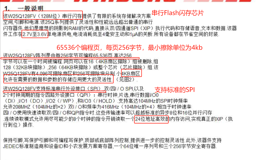
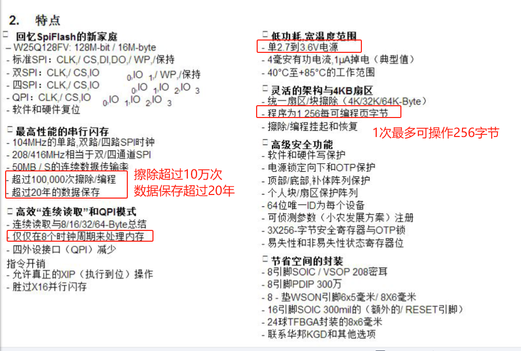
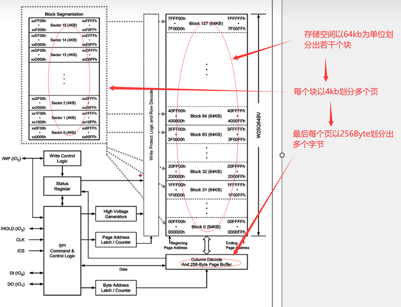
开发板中板载的主控芯片是STM32F407ZET6,主控芯片内部搭载512K的Flash闪存,但是用户程序是需要下载到Flash闪存空间的,所以留给用户的操作空间并不大,就为了用户的数据存储,可以使用外部串行Flash闪存芯片,开发板上板载的外部Flash芯片的型号是W25Q128,具体的特点如下图:
3.2内存分布
高电压生成器:实现FLASH掉电不丢失,击穿之后上电仍然记住击穿的状态
3.3基本模式
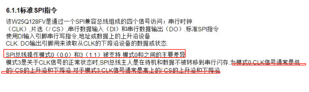
W25Q128芯片支持两种SPI模式(模式0和模式3),主机可以选择这两种模式的一种进行通信即可。
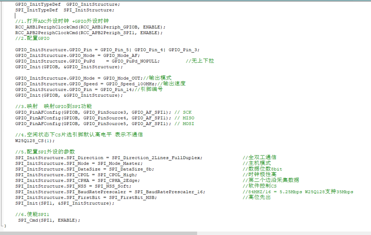
3.4代码配置
3.4.1初始化配置