华为AR路由器 典型配置案例——以太网交换
目录
Eth-Trunk
例:配置三层链路聚合
组网需求
操作步骤
检查配置结果
配置脚本
VLAN
举例:配置基于接口划分VLAN,实现同一VLAN内的互通(同设备)
组网需求
操作步骤
检查配置结果
配置脚本
举例:配置三层子接口实现不同VLAN间的互通
组网需求
操作步骤
检查配置结果
配置脚本
举例:配置VLANIF接口实现不同VLAN间的互通(同设备)
组网需求
操作步骤
检查配置结果
配置脚本
Eth-Trunk
例:配置三层链路聚合
组网需求
如图所示,DeviceA和DeviceB之间创建Eth-Trunk,将两个三层以太网接口捆绑成一个Eth-Trunk接口,可以增加带宽和提高可靠性。
注意:本例中interface1、interface2分别代表10GE0/0/1、10GE0/0/2。

操作步骤
- 在DeviceA和DeviceB上分别创建Eth-Trunk1并配置IP地址。
# 配置DeviceA。
<HUAWEI> system-view
[HUAWEI] sysname DeviceA
[DeviceA] interface eth-trunk 1
[DeviceA-Eth-Trunk1] undo portswitch
[DeviceA-Eth-Trunk1] ip address 10.1.1.1 24
# 配置DeviceB。
<HUAWEI> system-view [HUAWEI] sysname DeviceB [DeviceB] interface eth-trunk 1 [DeviceB-Eth-Trunk1] undo portswitch [DeviceB-Eth-Trunk1] ip address 10.1.1.2 24
- 向DeviceA和DeviceB的Eth-Trunk接口中加入成员接口。
# 配置DeviceA。
[DeviceB] interface eth-trunk 1
[DeviceA-Eth-Trunk1] port link-type trunk
[DeviceA-Eth-Trunk1] trunkport 10ge 0/0/1 to 0/0/2
[DeviceA-Eth-Trunk1] quit
# 配置DeviceB。
[DeviceB] interface eth-trunk 1
[DeviceB-Eth-Trunk1] port link-type trunk
[DeviceB-Eth-Trunk1] trunkport 10ge 0/0/1 to 0/0/2
[DeviceB-Eth-Trunk1] quit
检查配置结果
# 在任意视图下执行display interface eth-trunk命令,检查Eth-Trunk是否创建成功,及成员接口是否正确加入。
[DeviceA] display interface eth-trunk 1
Eth-Trunk1 current state : UP Line protocol current state : UP
Description:HUAWEI, AR Series, Eth-Trunk1 Interface
Route Port,Hash arithmetic : According to SIP-XOR-DIP,The Maximum Transmit Unit
is 1500 Internet Address is 10.1.1.1/24
IP Sending Frames' Format is PKTFMT_ETHNT_2, Hardware address is 00e0-fc12-3456
Current system time: 0000-0-00 00:00:00
Input bandwidth utilization  : 0.00%
Output bandwidth utilization : 0.00%
-----------------------------------------------------
PortName                Status              Weight
-----------------------------------------------------
10GE0/0/1               UP                  1
10GE0/0/2               UP                  1
-----------------------------------------------------
The Number of Ports in Trunk : 2
The Number of UP Ports in Trunk : 2
# DeviceA和DeviceB的Eth-Trunk接口能够相互Ping通。
[RouterA] ping -a 10.1.1.1 10.1.1.2   PING 10.1.1.2: 56  data bytes, press CTRL_C to break     Reply from 10.1.1.2: bytes=56 Sequence=1 ttl=255 time=31 ms     Reply from 10.1.1.2: bytes=56 Sequence=2 ttl=255 time=31 ms     Reply from 10.1.1.2: bytes=56 Sequence=3 ttl=255 time=62 ms     Reply from 10.1.1.2: bytes=56 Sequence=4 ttl=255 time=62 ms     Reply from 10.1.1.2: bytes=56 Sequence=5 ttl=255 time=62 ms
--- 10.1.1.2 ping statistics ---     5 packet(s) transmitted     5 packet(s) received     0.00% packet loss    round-trip min/avg/max = 31/49/62 ms
配置脚本
-
DeviceA
#
sysname DeviceA
#
interface Eth-Trunk1ip address 10.1.1.1 255.255.255.0
#
interface 10GE0/0/1 eth-trunk 1
#
interface 10GE0/0/2eth-trunk 1
#
return
-
DeviceB
#
sysname DeviceB
#
interface Eth-Trunk1ip address 10.1.1.2 255.255.255.0
#
interface 10GE0/0/1 eth-trunk 1
#
interface 10GE0/0/2eth-trunk 1
#
return
VLAN
举例:配置基于接口划分VLAN,实现同一VLAN内的互通(同设备)
组网需求
如图1-2所示,把连接Host1和Host2的接口划分到VLAN2,把连接Host3和Host4的接口划分到VLAN3,实现同一VLAN内的主机可以通信,不同VLAN内的主机不能直接二层通信。
- Host1和Host2可以互相通信,Host3和Host4可以互相通信。
- Host1和VLAN3内的Host3、Host4不能互相通信,Host2和VLAN3内的Host3、Host4不能互相通信。
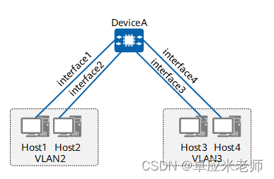
图1-2 基于接口划分VLAN组网图(同设备)
注意:本例中interface1、interface2、interface3、interface4分别代表10GE0/0/1、10GE0/0/2、10GE0/0/3、10GE0/0/4。
操作步骤
- 创建VLAN,并配置设备与主机相连的接口为Access类型接口。
<HUAWEI> system-view
[HUAWEI] sysname DeviceA
[DeviceA] vlan batch 2 3
[DeviceA] interface 10ge 0/0/1
[DeviceA-10GE0/0/1] portswitch
[DeviceA-10GE0/0/1] port link-type access
[DeviceA-10GE0/0/1] quit
[DeviceA] interface 10ge 0/0/2
[DeviceA-10GE0/0/2] portswitch
[DeviceA-10GE0/0/2] port link-type access
[DeviceA-10GE0/0/2] quit
[DeviceA] interface 10ge 0/0/3
[DeviceA-10GE0/0/3] portswitch
[DeviceA-10GE0/0/3] port link-type access
[DeviceA-10GE0/0/3] quit
[DeviceA] interface 10ge 0/0/4
[DeviceA-10GE0/0/4] portswitch
[DeviceA-10GE0/0/4] port link-type access
[DeviceA-10GE0/0/4] quit
- 配置接口加入VLAN。
# 将10GE0/0/1和10GE0/0/2接口加入VLAN2。
[DeviceA] vlan 2
[DeviceA-vlan2] port 10ge 0/0/1 to 0/0/2
[DeviceA-vlan2] quit
# 将10GE0/0/3和10GE0/0/4接口加入VLAN3。
[DeviceA] vlan 3
[DeviceA-vlan3] port 10ge 0/0/3 to 0/0/4
[DeviceA-vlan3] quit
检查配置结果
# 执行display vlan命令可以查看VLAN状态。
[DeviceA] display vlan
The total number of vlans is : 2
--------------------------------------------------------------------------------
U: Up;         D: Down;         TG: Tagged;         UT: Untagged;
MP: Vlan-mapping;               ST: Vlan-stacking;
#: ProtocolTransparent-vlan;    *: Management-vlan;
MAC-LRN: MAC-address learning;  STAT: Statistic;
BC: Broadcast; MC: Multicast;   UC: Unknown-unicast;
FWD: Forward;  DSD: Discard;
--------------------------------------------------------------------------------VID          Ports
--------------------------------------------------------------------------------2         UT:10GE0/0/1(U)   10GE0/0/2(U)3         UT:10GE0/0/3(U)   10GE0/0/4(U)VID  Type     Status  Property  MAC-LRN STAT    BC  MC  UC  Description
--------------------------------------------------------------------------------2 common   enable  default   enable  disable FWD FWD FWD VLAN 00023 common   enable  default   enable  disable FWD FWD FWD VLAN 0003
# VLAN2的主机无法Ping通VLAN3内的主机,但是同一VLAN内的主机可以互相Ping通。
配置脚本
#
sysname DeviceA
#
vlan batch 2 to 3
#
interface 10GE0/0/1portswitchport link-type accessport default vlan 2
#
interface 10GE0/0/2portswitchport link-type accessport default vlan 2
#
interface 10GE0/0/3portswitchport link-type accessport default vlan 3
#
interface 10GE0/0/4portswitchport link-type accessport default vlan 3
#
return
举例:配置三层子接口实现不同VLAN间的互通
组网需求
如图1-3所示,VLAN2内的主机和VLAN3内的主机位于不同的网段。希望在DeviceA上配置三层子接口,实现VLAN2与VLAN3之间的主机互通。
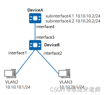
图1-3 通过三层子接口实现不同VLAN间的互通组网图
注意:本例中interface1、interface2、interface3、interface4分别代表10GE0/0/1、10GE0/0/2、10GE0/0/3、10GE0/0/4。
操作步骤
- 在DeviceB上创建VLAN。
<HUAWEI> system-view
[HUAWEI] sysname DeviceB
[DeviceB] vlan batch 2 3
[DeviceB] interface 10ge 0/0/1
[DeviceB-10GE0/0/1] portswitch
[DeviceB-10GE0/0/1] port link-type access
[DeviceB-10GE0/0/1] port default vlan 2
[DeviceB-10GE0/0/1] quit
[DeviceB] interface 10ge 0/0/2
[DeviceB-10GE0/0/2] portswitch
[DeviceB-10GE0/0/2] port link-type access
[DeviceB-10GE0/0/2] port default vlan 3
[DeviceB-10GE0/0/2] quit
- 在DeviceB的接口10GE0/0/3上配置允许用户所属的VLAN通过。
[DeviceB] interface 10ge 0/0/3
[DeviceB-10GE0/0/3] portswitch
[DeviceB-10GE0/0/3] port link-type trunk
[DeviceB-10GE0/0/3] port trunk allow-pass vlan 2 3
[DeviceB-10GE0/0/3] quit
- 在DeviceA上创建子接口并关联VLAN。
<HUAWEI> system-view
[HUAWEI] sysname DeviceA
[DeviceA] interface 10ge 0/0/4
[DeviceA-10GE0/0/4] undo portswitch
[DeviceA-10GE0/0/4] quit
[DeviceA] interface 10ge 0/0/4.1
[DeviceA-10GE0/0/4.1] dot1q termination vid 2
[DeviceA-10GE0/0/4.1] quit
[DeviceA] interface 10ge 0/0/4.2
[DeviceA-10GE0/0/4.2] dot1q termination vid 3
[DeviceA-10GE0/0/4.2] quit
- 在DeviceA上配置IP地址。
[DeviceA] interface 10ge 0/0/4.1
[DeviceA-10GE0/0/4.1] ip address 10.10.10.2 24
[DeviceA-10GE0/0/4.1] quit
[DeviceA] interface 10ge 0/0/4.2
[DeviceA-10GE0/0/4.2] ip address 10.10.20.2 24
[DeviceA-10GE0/0/4.2] quit
检查配置结果
在VLAN2的主机上配置缺省网关为接口10GE0/0/4.1的IP地址10.10.10.2/24,在VLAN3的主机上配置缺省网关为接口10GE0/0/4.2的IP地址10.10.20.2/24。配置完成后,VLAN2和VLAN3之间的主机能够相互Ping通。
配置脚本
- DeviceA
#
sysname DeviceA
#
interface 10GE0/0/4
#
interface 10GE0/0/4.1ip address 10.10.10.2 255.255.255.0encapsulation dot1q-terminationdot1q termination vid 2
#
interface 10GE0/0/4.2ip address 10.10.20.2 255.255.255.0encapsulation dot1q-terminationdot1q termination vid 3
#
return
- DeviceB
#
sysname DeviceB
#
vlan batch 2 to 3
#
interface 10GE0/0/1portswitchport link-type accessport default vlan 2
#
interface 10GE0/0/2portswitchport link-type accessport default vlan 3
#
interface 10GE0/0/3portswitchport link-type trunkport trunk allow-pass vlan 2 to 3
#
return
举例:配置VLANIF接口实现不同VLAN间的互通(同设备)
组网需求
如图1-4所示,DeviceA下的主机被划分到不同的VLAN中,分别是VLAN2和VLAN3,且位于不同的网段。希望实现VLAN2和VLAN3之间相互通信。
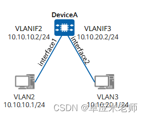
图1-4 配置VLANIF接口实现不同VLAN间的互通组网图(同设备)
注意:本例中interface1、interface2分别代表10GE0/0/1、10GE0/0/2。
操作步骤
- 创建VLAN,并配置接口加入VLAN。
<HUAWEI> system-view
[HUAWEI] sysname DeviceA
[DeviceA] vlan batch 2 3
[DeviceA] interface 10ge 0/0/1
[DeviceA-10GE0/0/1] portswitch
[DeviceA-10GE0/0/1] port link-type access
[DeviceA-10GE0/0/1] port default vlan 2
[DeviceA-10GE0/0/1] quit
[DeviceA] interface 10ge 0/0/2
[DeviceA-10GE0/0/2] portswitch
[DeviceA-10GE0/0/2] port link-type access
[DeviceA-10GE0/0/2] port default vlan 3
[DeviceA-10GE0/0/2] quit
- 配置VLANIF接口的IP地址。
[DeviceA] interface vlanif 2
[DeviceA-Vlanif2] ip address 10.10.10.2 24
[DeviceA-Vlanif2] quit
[DeviceA] interface vlanif 3
[DeviceA-Vlanif3] ip address 10.10.20.2 24
[DeviceA-Vlanif3] quit
检查配置结果
在VLAN2中的主机上配置IP地址为10.10.10.1/24,缺省网关为接口VLANIF2的IP地址10.10.10.2/24,在VLAN3中的主机上配置IP地址为10.10.20.1/24,缺省网关为接口VLANIF3的IP地址10.10.20.2/24。配置完成后,VLAN2中的主机与VLAN3中的主机能够相互Ping通。
配置脚本
#
sysname DeviceA
#
vlan batch 2 to 3
#
interface Vlanif2ip address 10.10.10.2 255.255.255.0
#
interface Vlanif3ip address 10.10.20.2 255.255.255.0
#
interface 10GE0/0/1portswitchport link-type accessport default vlan 2
#
interface 10GE0/0/2portswitchport link-type accessport default vlan 3
#
return