MCU软核 3. Xilinx Artix7上运行cortex-m3软核
0. 环境
- win10 + vivado 2018.3 + keil mdk
- jlink
- XC7A35TV12
1. 下载资料
https://keilpack.azureedge.net/pack/Keil.V2M-MPS2_DSx_BSP.1.1.0.pack
https://gitee.com/whik/cortex_m3_on_xc7a100t
2. vivado 2018
Create Project -> Next ->
-> Project name: cortex_m3
-> Project location: E:/Workspaces/vivado2018/XC7A35TV12/
-> 取消勾选 Create project subdirectory
-> RTL Project
-> Next -> Next
-> xc7a35tftg256-1
-> finish
创建Block Design
点击IP INTEGRATOR下的 Create Block Design -> Design name: cm3_core -> OK
2.1 添加m3 ip核
把
mcu designstart cortex-m3\cortex_m3_on_xc7a100t-main\cm3_core
拷贝到
E:\Workspaces\vivado2018\XC7A35TV12\cortex_m3\cm3_core

-> 点击PROJECT MANAGER下的Settings -> IP -> Repository -> Add -> E:\Workspaces\vivado2018\XC7A35TV12\cortex_m3\cm3_core
-> Apply -> OK
添加Cortex-M3
点击Diagram下的+ -> 筛选并双击Cortex-M3 -> 双击新建的实例CORTEXM3_AXI_0 ->
-> Debug -> Trace Level: 0 = No trace -> 取消勾选 JTAG Port Present
-> Instruction Memory -> ITCM Size: 64kB -> 取消勾选 Initialise ITCM
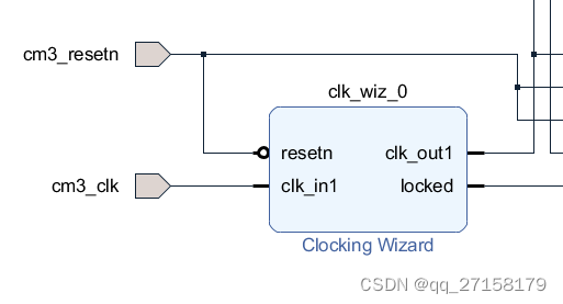
2.2 Clocking Wizard
点击Diagram下的+ -> 筛选并双击Clocking Wizard -> 双击新建的实例 clk_wiz_0 ->
-> Clocking Options -> Primary 50MHz ->
-> Output Clocks -> clk_out1: 50MHz ->
-> Reset Type: Active Low
-> OK
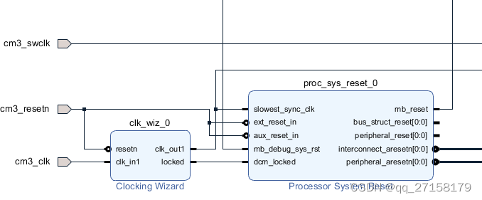
2.3 复位
点击Diagram下的+ -> 筛选并双击Processor System Reset -> OK
点击Diagram下的+ -> 筛选并双击 Utility Vector Logic -> 双击新建的实例 util_vector_logic_0 ->
-> C_SIZE: 1 -> not -> OK
2.4 AXI
点击Diagram下的+ -> 筛选并双击 AXI Interconnect -> OK
File -> Add Sources -> Add or create design sources -> Next
-> Create File -> swdiobuf -> OK
-> Finish
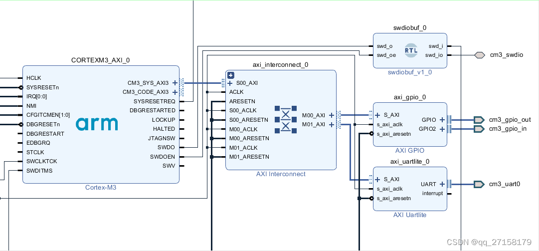
2.5 SWD调试口
修改swdiobuf.v
添加以下内容:
module swdiobuf(input swd_o,output swd_i,input swd_oe,inout swd_io);IOBUF swd_iobuf_inst1(.O(swd_i),.I(swd_o),.IO(swd_io),.T(~swd_oe) //);endmoduleSources -> Design Sources -> -> 右键选择swdiobuf -> Add Module to Block Design
连线
CORTEXM3_AXI_0 swdiobuf_0
SWDO swd_o
SWDOEN swd_oe
SWDITMS swd_i
右键swd_io -> Make External -> 改名为 cm3_swdio
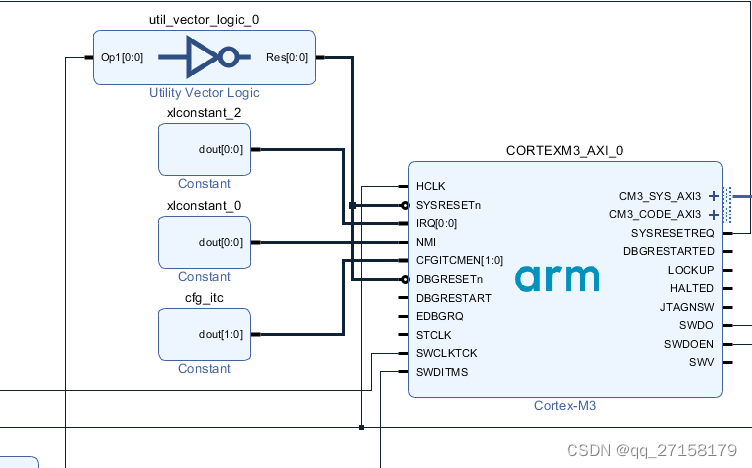
2.6 cortex-m3的接口配置
点击Diagram下的+ -> 筛选并双击 Constant -> 双击新建的实例 xlconstant_0 -> Const Width: 1 -> ConstVal: 0 -> OK -> 输出连线 NMI
点击Diagram下的+ -> 筛选并双击 Constant -> 双击新建的实例 xlconstant_1 -> Const Width: 2 -> ConstVal: 1 -> OK -> 改名为 cfg_itc -> 输出连线 CFGITCMEN
点击Diagram下的+ -> 筛选并双击 Constant -> 双击新建的实例 xlconstant_2 -> Const Width: 1 -> ConstVal: 1 -> OK -> 改名为 cfg_itc -> 输出连线 IRQ
2.7 外设
点击Diagram下的+ -> 筛选并双击 AXI GPIO -> 双击新建的实例 axi_gpio_0 ->
-> GPIO -> 勾选All Outputs -> GPIO Width: 4
-> 勾选 Enable Dual Channel
-> GPIO 2 -> 勾选All Inputs -> GPIO Width: 4
-> OK
点击Diagram下的+ -> 筛选并双击 AXI Uartlite -> 双击新建的实例 axi_uartlite_0 ->
-> Baud Rate: 115200
-> OK
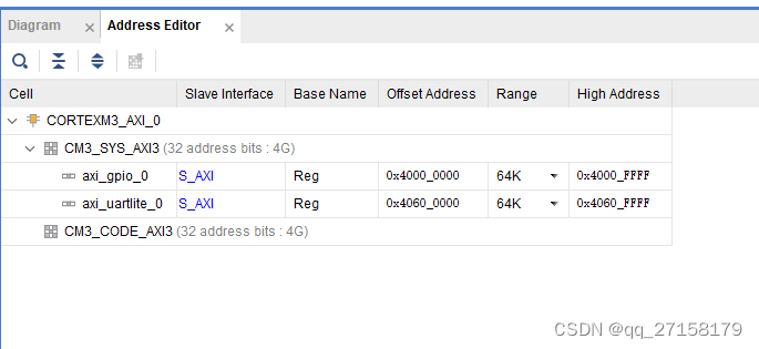
2.8 分配外设基地址
Address Editor -> Auto Assign Address
2.9 验证
右键空白处 -> Validate Design
2.10 封装
点击 IP INTEGRATOR下的 Generate Block Design -> global -> Generate
Sources -> 右键 microblaze_core -> Create HDL wrapper -> Copy generated wrapper to allow user edits -> OK
2.11 封装 top
Sources -> Add Sources -> -> 右键选择 s wdiobuf -> Add Module to Block Design
File -> Add Sources -> Add or create design sources -> Next
-> Create File -> top_hdl -> OK
-> Finish
module top_hdl(//Inputsinput clk,input rst_n,input swclk,input uart_rxd,input [3:0] sw,//Outputsoutput [3:0] led,output uart_txd,//Inoutsinout swdio
);cm3_core_wrapper cm3_core_wrapper_ut0(//Inputs.cm3_clk(clk),.cm3_resetn(rst_n),.cm3_gpio_in_tri_i(sw[3:0]),.cm3_swclk(swclk),.cm3_uart0_rxd(uart_rxd),//Outputs.cm3_gpio_out_tri_o(led[3:0]),.cm3_uart0_txd(uart_txd),//Inouts.cm3_swdio(swdio)
);endmodule   //top_hdl end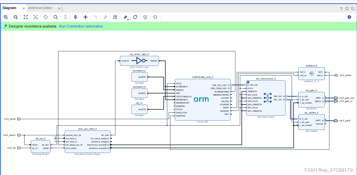
2.12 编译
RTL ANALYSIS -> Schematic
-> I/O Ports
-> save... -> cortex_m3.xdc
2.13 修改约束文件 cortex_m3.xdc
set_property PACKAGE_PIN D4 [get_ports clk_50m]
set_property IOSTANDARD LVCMOS33 [get_ports clk_50m]set_property PACKAGE_PIN C4 [get_ports rst_n]
set_property IOSTANDARD LVCMOS33 [get_ports rst_n]set_property PACKAGE_PIN K12 [get_ports {led[0]}]
set_property IOSTANDARD LVCMOS33 [get_ports {led[0]}]set_property PACKAGE_PIN L14 [get_ports {led[1]}]
set_property IOSTANDARD LVCMOS33 [get_ports {led[1]}]set_property PACKAGE_PIN L13 [get_ports {led[2]}]
set_property IOSTANDARD LVCMOS33 [get_ports {led[2]}]set_property PACKAGE_PIN M14 [get_ports {led[3]}]
set_property IOSTANDARD LVCMOS33 [get_ports {led[3]}]set_property PACKAGE_PIN D11 [get_ports {key[0]}]
set_property IOSTANDARD SSTL15 [get_ports {key[0]}]set_property PACKAGE_PIN G11 [get_ports {key[1]}]
set_property IOSTANDARD SSTL15 [get_ports {key[1]}]set_property PACKAGE_PIN H11 [get_ports {key[2]}]
set_property IOSTANDARD SSTL15 [get_ports {key[2]}]set_property PACKAGE_PIN K13 [get_ports {key[3]}]
set_property IOSTANDARD LVCMOS33 [get_ports {key[3]}]set_property PACKAGE_PIN E6 [get_ports uart_txd]
set_property IOSTANDARD LVCMOS33 [get_ports uart_txd]set_property PACKAGE_PIN C7 [get_ports uart_rxd]
set_property IOSTANDARD LVCMOS33 [get_ports uart_rxd]set_property PACKAGE_PIN M15 [get_ports swclk]
set_property IOSTANDARD LVCMOS33 [get_ports swclk]
set_property CLOCK_DEDICATED_ROUTE FALSE [get_nets swclk_IBUF]set_property PACKAGE_PIN R16 [get_ports swdio]
set_property IOSTANDARD LVCMOS33 [get_ports swdio]#set_property BITSTREAM.CONFIG.UNUSEDPIN Pulldown [current_design]
#set_property BITSTREAM.CONFIG.UNUSEDPIN Pullup [current_design]
set_property BITSTREAM.CONFIG.UNUSEDPIN Pullnone [current_design]set_property BITSTREAM.CONFIG.SPI_32BIT_ADDR NO [current_design]
set_property BITSTREAM.CONFIG.SPI_BUSWIDTH 4 [current_design]
set_property BITSTREAM.CONFIG.SPI_FALL_EDGE YES [current_design]
编译
-> Run Systhesis
-> Run Implementation
-> Generate Bitstream
下载
Open Hardware Manager -> Open Target -> Auto Connect -> 右键Hardware栏内的xc7a35t_0 -> 点击Program device
-> Bitstream file: E:/Workspaces/vivado2018/XC7A35TV12/cortex_m3/vivado/cortex_m3.runs/impl_1/top_hdl.bit
固化
Tools -> Generate Memory Configuration File ->
-> MCS
-> 128MB
-> File name: E:/Workspaces/vivado2018/XC7A35TV12/cortex_m3/vivado/cortex_m3.runs/impl_1/cortex_m3.mcs
-> Interface: SPIx4
-> 勾选 Load bitstream files
-> Bitfile: E:/Workspaces/vivado2018/XC7A35TV12/cortex_m3/vivado/cortex_m3.runs/impl_1/top_hdl.bit
请先手动删除
E:/Workspaces/vivado2018/XC7A35TV12/cortex_m3/vivado/cortex_m3.runs/impl_1
下的
led_test.mcs
led_test.prm
-> OK
-> Add Configuration Memory Device -> 输入n25q128-3.3v -> OK
烧写
-> Configuration file: E:/Workspaces/vivado2018/XC7A35TV12/cortex_m3/vivado/cortex_m3.runs/impl_1/cortex_m3.mcs
-> PRM file: E:/Workspaces/vivado2018/XC7A35TV12/cortex_m3/vivado/cortex_m3.runs/impl_1/cortex_m3.prm
-> OK
3. keil
3.1 安装器件库
直接双击Keil.V2M-MPS2_DSx_BSP.1.1.0.pack安装
3.2 新建工程
Project -> New uVision Project -> E:\Workspaces\vivado2018\XC7A35TV12\cortex_m3\mdk\ds_cm3
-> Select Device for Target -> ARM -> ARM Cortex M3 -> DS_CM3 -> OK
-> 勾选 CMSIS 下的 CORE
-> 勾选 Device 下的 Startup
-> OKFile -> New
添加以下内容
#include "DS_CM3.h"
#include "system_DS_CM3.h"int main(void)
{while(1){}
}
保存到
E:\Workspaces\vivado2018\XC7A35TV12\cortex_m3\mdk\src\main.c
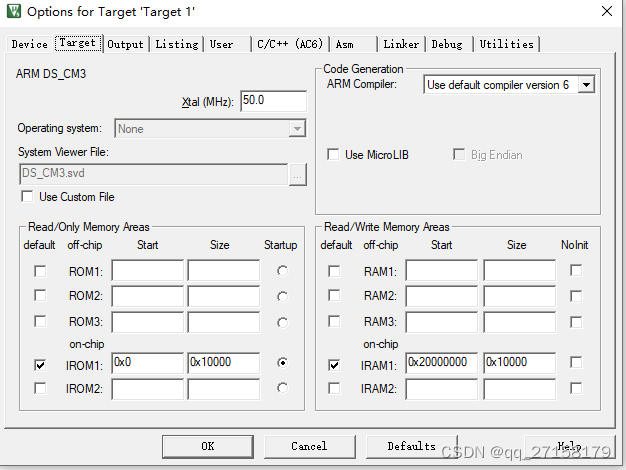
设置RAM和ROM地址
在工程选项中设置片上ITCM的起始地址0x0、大小64K,片上DTCM起始地址0x20000000、大小64K:
Options for Target -> Target ->
-> IROM1: Start: 0x0, Size: 0x10000,
-> IRAM1: Start: 0x20000000, Size: 0x10000,
3.3 修改main.c
main.c直接使用mcu designstart cortex-m3\cortex_m3_on_xc7a100t-main\mdk_prj\application\main.c
3.4 Flash编程算法生成
文件浏览器 打开D:\Keil\mdk5\ARM\Flash
把
D:\Keil\mdk5\ARM\Flash\_Template
拷贝到
D:\Keil\mdk5\ARM\Flash\DS_CM3
双击 D:\Keil\mdk5\ARM\Flash\DS_CM3\NewDevice.uvprojx打开FlashDev.c
把里面的
struct FlashDevice const FlashDevice  =  {FLASH_DRV_VERS,             // Driver Version, do not modify!"New Device 256kB Flash",   // Device Name ONCHIP,                     // Device Type0x00000000,                 // Device Start Address0x00040000,                 // Device Size in Bytes (256kB)1024,                       // Programming Page Size0,                          // Reserved, must be 00xFF,                       // Initial Content of Erased Memory100,                        // Program Page Timeout 100 mSec3000,                       // Erase Sector Timeout 3000 mSec// Specify Size and Address of Sectors0x002000, 0x000000,         // Sector Size  8kB (8 Sectors)0x010000, 0x010000,         // Sector Size 64kB (2 Sectors) 0x002000, 0x030000,         // Sector Size  8kB (8 Sectors)SECTOR_END
};
修改为:
struct FlashDevice const FlashDevice  =  {FLASH_DRV_VERS,             // Driver Version, do not modify!"MyCM3onFPGA",              // Device Name ONCHIP,                     // Device Type0x00000000,                 // Device Start Address0x00010000,                 // 修改为64KB1024,                       // Programming Page Size0,                          // Reserved, must be 00xFF,                       // Initial Content of Erased Memory100,                        // Program Page Timeout 100 mSec3000,                       // Erase Sector Timeout 3000 mSec// Specify Size and Address of Sectors0x010000, 0x000000,         // 只有一个扇区,起始地址为0SECTOR_END
};
编译,生成D:\Keil\mdk5\ARM\Flash\DS_CM3\NewDevice.FLM
把这个文件拷贝到
D:\Keil\mdk5\ARM\Flash\DS_CM3.FLM
回到ds_cm3.uvprojx工程
-> 右键 Target 1 -> Options for target -> Debug -> Use J-LINK -> Settings ->
-> Flash Download -> Add -> MyCM3onFPGA -> Add
3.5 下载测试
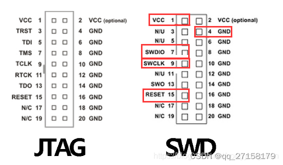
下载时使用jlink的swdio、swclk、gnd连接fpga板卡上的对应三根线即可。
下载时通过keil的 Flash -> Download开始下载。
有时候下载完需要按下复位才可以执行。
参考
[1]在FPGA上搭建Cortex-m3软核,https://blog.csdn.net/m0_50735735/article/details/124253664
[2]手把手教你在FPGA上运行一个ARM Cortex-M3软核,https://zhuanlan.zhihu.com/p/489213515
[3]ARM Cortex M3 verilog源代码 Cortex-M3 DesignStart评估,https://www.amobbs.com/thread-5756149-1-1.html
[4]如何用FPGA实现一个ARM Cortex-M3软核,https://blog.csdn.net/whik1194/article/details/123784346